
Have you ever needed a reliable framework to support piping, conduit, or cable trays and wondered how to install channel strut correctly?
Channel Strut Installation Guide
This guide gives you a comprehensive, step-by-step approach to planning, selecting, installing, and maintaining channel strut systems. You’ll find practical tips, safety reminders, tables for common selections, and pointers to applicable codes so you can complete installations that are safe and durable.
What is channel strut?
Channel strut (often called Unistrut, strut channel, or simply “strut”) is a standardized metal framing system used to support mechanical, electrical, and plumbing components. It provides a modular and adjustable framework that reduces fabrication time and simplifies on-site modifications.
Why use channel strut?
You use channel strut because it saves time, allows flexibility, and reduces the need for welding or custom brackets. It’s adaptable to many applications, from supporting HVAC ductwork and piping to hanging lighting or solar arrays.
Types of channel strut
There are several profiles and materials of channel strut, each suited to specific environments and loads. Understanding the differences helps you choose the right product for your application.
Common profiles
- Type 1 (standard 1-5/8″ width): The most common, compatible with many fittings and hardware.
- Type 2 (wide profile, 2-1/2″ or 2″): Used when larger fittings or increased load distribution is needed.
- Slotted vs. un-slotted: Slotted channels have pre-punched holes for bolts and anchoring, while un-slotted provide continuous strength and allow custom hole placement.
Materials and finishes
- Galvanized steel: Most common for indoor and many outdoor applications; offers corrosion resistance.
- Stainless steel: Used in corrosive environments, food processing, or where higher corrosion protection is required.
- Aluminum: Lighter weight, non-magnetic, suitable for lighter loads and non-corrosive outdoor exposure.
- Painted or powder-coated: Adds aesthetic and supplemental corrosion protection.
Fittings and accessories
You’ll find fittings like tees, angles, couplers, and beam clamps that let you create rigid structures without welding. Not all fittings are interchangeable between brands, so check compatibility.
Tools and materials you’ll need
Gathering the right tools and materials before starting saves trips and keeps the job efficient. Below are typical items you’ll need for most installations.
Essential tools
- Tape measure, combination square, and level
- Hacksaw, reciprocating saw, or band saw with appropriate blade for metal
- Drill and metal bits
- Wrenches or sockets (sizes matching bolt hardware)
- Torque wrench (for critical or labeled bolts)
- Punch or center punch for marking
- Personal protective equipment (glasses, gloves, hearing protection)
Common materials and hardware
- Channel strut sections (of selected length and profile)
- Channel nuts (spring nuts or serrated nuts) and bolts
- Threaded rod, anchor bolts, or toggle bolts for mounting to structure
- End caps, brackets, couplers, and clamps as required
- Washers and lock washers or locknuts where necessary
Planning your installation
Planning avoids rework and ensures the installed system meets load and code requirements. You should assess loads, attachment points, spacing, and the routing of cables or pipes before cutting metal or drilling anchor holes.
Site assessment
Inspect the structure where you’ll attach strut. Identify load-bearing members, locate studs or beam flanges, and note any obstructions. Understand whether attachments are to concrete, steel, wood, or masonry to select proper anchors.
Load considerations
Decide the total weight the strut will carry, including dead loads (pipes, trays) and live loads (maintenance personnel, water-filled pipes). Add a safety factor as required by codes or project specifications. If in doubt, consult a structural engineer.
Routing and clearances
Plan run direction, access for installation, and service clearance for maintenance. Keep sufficient space for hanger installation and future expansion when feasible.
Measuring and cutting channel strut
Accurate measuring and clean cuts create a professional installation. Mark twice, cut once is a good rule to follow.
Measuring tips
Measure from fixed reference points and include allowances for connectors and couplers. When multiple repetitive lengths are needed, create a template to save time and ensure consistency.
Cutting and deburring
Use a saw suited for metal to avoid tearing or deformation. After cutting, remove burrs and sharp edges to protect installers and cable insulation. A file or deburring tool works well for the inside edges.
Fastening methods and hardware selection
Choosing the correct fasteners and fittings affects both strength and ease of installation. Use hardware rated for the environment and loads you calculated.
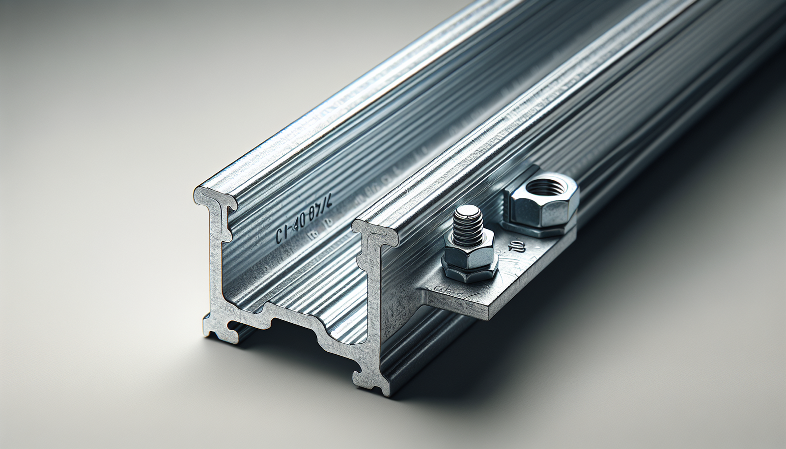
Channel nuts and bolts
Spring or serrated channel nuts slide into the channel and provide an anchor for bolts. Serrated nuts create a more secure connection and resist rotation; spring nuts help hold the nut in place during assembly.
Anchor types
- Wedge anchors: Common for solid concrete attachments; provide high pullout strength.
- Sleeve anchors: Suitable for concrete and masonry, require proper hole sizing.
- Bolt-through with backing plate: Used when access is available on both sides of a member.
- Toggle or hollow-wall anchors: For light loads in hollow substrates.
- Beam clamps: Attach to I-beam flanges without drilling.
Recommended bolt sizes and torque
Use bolts sized to the load, typically 1/4″, 5/16″, 3/8″, 1/2″ diameter common in strut systems. Below is a quick reference table for typical bolt sizes and approximate torque values; verify with manufacturer specs and use a torque wrench where required.
| Bolt Diameter | Typical Grade | Approx. Torque (ft-lb) | Common Use |
|---|---|---|---|
| 1/4″ | Grade 5 | 5–8 | Light fittings, small clamps |
| 5/16″ | Grade 5 | 12–15 | Medium pipe supports, light trays |
| 3/8″ | Grade 5 | 20–30 | Heavy trays, larger pipes |
| 1/2″ | Grade 5 | 60–70 | Primary hangers, structural anchors |
Always follow bolt manufacturer torque specifications and consider lock washers or thread-lock where vibration is expected.
Mounting to different substrates
Different substrates require different anchor choices and installation techniques. Below are general guidelines for common materials.
Concrete
Use wedge or sleeve anchors sized for the load. Drill the hole to the specified depth, clean the dust, insert the anchor, and torque per manufacturer instructions. For high loads, consider through-bolting with backing plate.
Steel
Attach using beam clamps, welded brackets (if allowed), or bolt through existing holes. When bolting, ensure flange thickness and bolt grade are suitable for the design load.
Wood
Use lag screws or bolts into structural members like joists or studs. Pre-drill pilot holes and use washers under the head to distribute load and prevent embedded heads.
Hollow masonry or block
Use epoxy anchors for higher loads or expansion anchors designed for hollow masonry. For light loads, sleeve or toggle anchors may suffice.
Typical spacing and support guidelines
Spacing of hangers and supports affects deflection and load distribution. Below are general recommended spacings; use these as starting points and confirm with manufacturer tables and local codes.
Pipe and conduit support spacing (general guidelines)
- Small conduit and light piping (up to 1″) — supports every 4–6 ft
- Medium piping (1″ to 2-1/2″) — supports every 3–6 ft depending on material
- Large piping and heavy drainage — supports every 2–4 ft as required by code or engineer
Cable tray and ladder support spacing
- Small trays with light cable load — supports every 5–8 ft
- Larger trays with heavy loading — supports every 3–5 ft
Strut beam deflection
For long unsupported spans, consider using two channels joined back-to-back or using bridging to increase moment of inertia and reduce deflection. When in doubt, refer to manufacturer load tables or consult a structural engineer.
Assembly techniques and best practices
Correct assembly keeps the system stable and easy to adjust later. These tips help you install cleanly and efficiently.
Using channel nuts
Insert the channel nut into the open face of the strut and turn it so the nut threads engage with the channel lips. For spring nuts, compress the spring and slide to position. Tighten bolts to snug; final torque may be required by spec.
Joining sections
When you need continuous runs, use couplers or back-to-back plates joined with bolts. Ensure alignment and that couplers are fully engaged before tightening to the final torque.
Leveling and squaring
Use temporary shims or adjustable hangers to level long runs. Square corner assemblies with a carpenter’s square before final tightening.
Grounding and electrical considerations
When supporting electrical equipment, you must consider grounding, bonding, and potential current-carrying capacity. Improper grounding can be dangerous.
Bonding metallic channels
If the channel supports cable trays, raceways, or equipment that requires grounding, ensure continuous electrical continuity. Mechanical joints using standard channel fittings may not provide low-resistance bonding; you may need bonding jumpers (flexible copper jumpers) across joints.
Code compliance
Follow the National Electrical Code (NEC) and local amendments for grounding and bonding requirements. Conduit, cable tray, and equipment must be properly connected to the grounding system.
Seismic and wind considerations
In seismic regions or for outdoor installations exposed to wind, additional bracing and anchorage precautions are necessary to resist lateral loads.
Seismic bracing
Install lateral bracing, sway braces, and diagonals as required by local seismic design criteria. Hangers and connections should be sized and anchored to resist dynamic loads. Always refer to applicable seismic standards and a structural or mechanical engineer when in question.
Wind loads for outdoor runs
Use wind load calculations for long exposed runs, especially for solar arrays, ductwork, or large cable trays. Provide cross-bracing and increased anchorage where required.
Thermal expansion and contraction
Long runs of supported piping or ductwork will move with temperature changes. Allow for this movement to prevent stress in hangers and supports.
Sliding supports and anchors
Design a system of fixed anchors and sliding supports. Fixed anchors lock the component at a defined point while sliding supports allow thermal expansion away from the anchor.
Expansion loops and offsets
When necessary, include expansion loops or offsets in the piping or duct design so thermal movement does not over-stress connections or equipment.
Step-by-step installation procedure
This section provides a general step-by-step workflow you can follow for most channel strut installations. Adjust steps to fit project-specific drawings and specifications.
1. Confirm plans and materials
Verify that materials and fittings match the project specifications and that you have all required tools and hardware. Review layout drawings and field conditions.
2. Mark mounting points
Measure and mark attachment locations on the supporting structure. Use a level and plumb lines to ensure alignment across the run.
3. Drill and install anchors
Drill holes for anchors following manufacturer diameter and depth instructions. Clean holes in concrete and set anchors per instructions; tighten to specified torque.
4. Install main channel runs
Mount channel sections to the anchors or beam clamps. Use temporary fasteners if adjustments are needed before final tightening.
5. Assemble fittings and cross-members
Attach tees, angles, or couplers and assemble cross-members or bracing. Check squareness and alignment before locking fasteners.
6. Install equipment and piping
Place piping, conduit, or trays into the strut framework and secure with appropriate clamps or straps. Ensure safe and secure mounting while allowing for any needed movement.
7. Final torque and inspection
Tighten all bolts to specified torque values. Inspect the entire system visually and verify that supports are plumb, secure, and meet load and code requirements.
Maintenance and inspection
Routine inspections prolong the life of your channel strut system and reduce the risk of failures. Create a maintenance schedule based on environment and loading.
Periodic checks
- Inspect for loose bolts and re-torque as required.
- Check for corrosion or coating damage and repair promptly.
- Verify that moving supports are not seized and that expansion components are functioning.
Record keeping
Keep records of inspections, repairs, and any load changes. Documentation helps during audits, future modifications, and troubleshooting.
Troubleshooting common problems
When problems arise, systematic troubleshooting helps you find and fix the root cause.
Squeaking or movement
Loose bolts or worn bearings in sliding supports can cause noise. Tighten hardware and replace worn components.
Corrosion problems
If you find rust or coating failure, evaluate environmental conditions (humidity, chemicals) and consider upgrading to stainless steel or adding sacrificial corrosion protection.
Excessive deflection
If trays or pipes sag between supports, add intermediate supports or increase channel stiffness by pairing channels or using bridging members.
Codes, standards, and references
Compliance with codes and standards ensures safety and legal conformance. Familiarize yourself with the most applicable documents for your location and industry.
Typical references
- National Electrical Code (NEC) for electrical grounding and raceway support.
- International Building Code (IBC) for structural and seismic requirements.
- Manufacturer load tables and assembly instructions for product-specific constraints.
- Local building codes and municipal amendments.
When in doubt, consult a licensed structural or electrical engineer to verify designs that carry significant loads, span long distances, or are in critical service.
Example selection and sizing table
This example table gives a simplified illustration of strut selection conceptually. Use manufacturer catalogs and engineering calculations for definitive sizing.
| Application | Suggested Channel Type | Typical Hardware | Typical Max Span (approx.)* |
|---|---|---|---|
| Light conduit runs | 1-5/8″ slotted | 1/4″ bolts, spring nuts | 6–8 ft |
| Cable tray (medium load) | 2-1/2″ channel | 3/8″ bolts, serrated nuts | 4–6 ft |
| Heavy pipe or large tray | Back-to-back 1-5/8″ or 2-1/2″ | 1/2″ bolts, couplers | 3–4 ft |
*These spans are general guidelines. Confirm with manufacturer load tables and site-specific engineering.
Frequently asked questions
A short FAQ answers common concerns you might have during planning and installation.
Can you weld strut components?
Welding is possible on some strut materials but can void manufacturer warranty, damage protective coatings, and cause structural changes. When a welded connection is necessary, consult the manufacturer and a qualified welder.
Can different brands of strut be mixed?
Mixing brands can lead to compatibility issues with fittings and channel nuts. If you must mix, verify dimensions and confirm that fittings will seat correctly.
How do you handle unequal load distribution?
If loads are uneven, design the system with proper load paths and use stronger anchors or additional supports where loads are concentrated.
Final checklist before handover
Use this checklist to confirm readiness for project handover to operations or maintenance personnel.
- All anchors installed and torqued to specs.
- Channels aligned, plumb, and level.
- Equipment properly clamped and supported.
- Grounding and bonding completed where required.
- Documentation delivered: as-built drawings, torque records, material certificates, and inspection reports.
- Maintenance schedule provided.
Conclusion
By planning carefully, selecting suitable materials, and following correct installation practices, you’ll create a channel strut support system that is safe, adaptable, and long-lasting. If the installation involves significant loads, seismic criteria, or complex routing, consult a qualified engineer to confirm your design. With attention to detail and routine maintenance, your strut installation will serve effectively for years.